Analysis
The new design must meet the following requirements as specified by the client; they were based on improvements from the current machine in use. The bulleted list below outlines the improvements and features that the new machine must meet.
-
Take up less than 25ft2 of floor place
-
Able to plug into an 110v power outlet
-
Reassembly time takes less than 20 minutes
-
Preforms at least 10% more efficient than the current bag cutter
-
Needs to weigh in at less than 300lbs
-
Can handle 60-80 bags at a time
-
Maximum height of machine does not exceed 72 inches
-
Budget is no more than $1500, on parts and material, not including design time and labor
-
Bags must be 54 inches in length after being cut. Tolerances of ± 1 inch
-
External tool to cut material after winding process
-
The machine must be self-supporting. Required more than 70 lbs. to tip over at center of the shaft.
-
Able to cut 60-80 bags within 10 seconds
-
Powered by electric motor as per customer
The analysis for the machine started with finding the force it takes to remove material from the spool. The force found ranged from 2.5-7.5 lb. A safety factor of 1.33 was used to design for the upper limits of the force needed to get the material off the spool. Using the safety factor of 1.5 the new force was 10 lb. The force of 10 lb. acts at the top of the spinning board 13.5 inches from the center of the shaft. Using statics the torque required was 135 lb.-in or 11.25 lb.-ft. With torque found using the equation T = (P/Speed) the HP of the motor can be found. The HP needed is 0.128 hp. The hand calculations for motor size can be found in appendix A-2.
The calculations in A-2 shows the motor needs a minimum HP of 0.128, and 135 lb.-in of torque. The motor selected is a Bodine AC electric gear motor with ¼ HP supplying 162 lb.-in of torque. This motor has the closes HP and torque values needed to drive the machine.
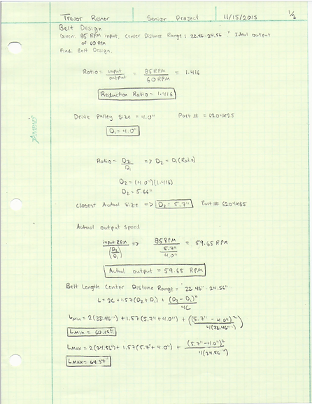
With the motor selected, the v-belt drive train can be designed. The motor input RPM of 85 RPM is ideal for a reduction ratio of 1.41 to 60 RPM. A driving sheave size of 4” was selected and driven size of 5.7” for the drive train. The size selected was guided by having good belt contact around the sheaves. The actual reduction ratio is 1.425 determined by the sheave size with an actual output RPM of 59.65. The center distance of the machine varies by 20.95 – 23.35”. The minimum belt length is 57.14” and maximum belt length is 61.96”. The average belt length was calculated to be 59.55” and the closest belt available was 59”. With the sheaves sizes being similar the angle of wrap for the 4” sheave is 175.54˚ and 184.45˚ for the 5.7” sheave. Because the drive train has a low RPM input the belt speed was calculated to be 89 ft./min. in Robert L. Mott’s Machine Elements in Mechanical Design textbook he recommends using an alternative way to transmit power at low speeds such as chain for gears. Because the maximum torque the motor will be applying is 162 lb.-in the low belt speed will be fine to use. Visit appendix A-3, A-4 and A-5 for hand calculations.
The parts transmitting all the torque needed to take material off the spools is a 3/16 square key way. 316 stainless steel was chosen as the key material because the machine could be with-in 500 ft. to a salt water bay. The 316 stainless steel is better for resisting corrosion than the 304. The minimum length was calculated to be 0.395”, both pulley hubs are over 1”, therefore the key length will be just the length of the hub. Visit in appendix A-9 for hand calculations.
For the machine to be self-supporting the force being applied to the spinning board must be smaller than the force to tip the machine over. With the machine having a center of mass of 160lb acting 22.5” from the bottom of the machine at the center. It will take 59lb to tip the over at the edge of the spinning board 60” from the ground. Another tipping force was found at the shaft of the machine, because this is the highest point on the machine a person could push from. If a person were to apply more than 73.3lb the machine would tip over. A design requirement specified by the owner was, it takes more than 70lb of force to tip the machine over at the shaft. All the tipping forces found were high enough where the base of the machine would not have to be widened. Visit appendix A-8 and A-11 for hand calculations.
The shellfish bag maker shaft has three stainless tabs welded to it. The weld size was calculated on each side of the tabs using a 2” weld length and a vertical shearing force of 120.4 lb. the calculated weld size was 0.002”. The weld size is very small and will just be a single pass weld. The calculated force of the tab was an extreme because it was only analysis as one tab taking all the force rather than being divided by three tabs. Visit appendix A-14 for hand calculations.
The frame of the machine is constructed from steel tube that will be welded together. The highest force the machine will feel is the motor on the machine locks up and isn’t spinning. The torque would be 162lb-in and the affected area would be where the side legs of the machine are connected to the tops sides. Using an equation listed in Robert L. Mott’s, textbook the weld size would be 0.005”. Again like the welded tabs to the shaft the force on the machine are rather small because the motor is relative small at ¼ HP. The whole machine will be welded together with a single pass weld. Visit appendix A-13 for hand calculations.
The shaft of the machine has a three tabs with two thread holes for bolts to hold the spinning board to the shaft. The bolts experience two types of loading vertical shear and a normal force from the torque. The six bolts were analysis under the condition that the board was locked up and the maximum torque was being applied of 162 lb.-in and 20 lb. weight of the aluminum plate that is the spinning board. The material was the bolts is 316 stainless steel with a yield of 30ksi. The shear stress was 705.4 psi for one bolt with the 20 lb. load. The normal force in tension from the moment was a force of 135.3 lb. divided by a diameter of 0.19” gave a normal stress of 4772 psi for one all under all the load. None of the bolts will fail because there under the yield of 316 stainless steel. Visit appendix A-11 for hand calculations.
The shellfish bag maker is power by 110v to power the gear motor that is driving the pulley system. A circuit was drawn to the build to under how the machine must be wired. See appendix A-15.
To see full analyses download document in overview